I made a few adjustments to my little tin can Stirling engine. It now spins twice as fast, at a rate of around 210rpm. Not that that means much because the more flame you put under it the faster it goes. But its around twice as fast as it was originally. Quite a success as far as bettering a terribly inefficient Stirling engine goes.
If you ask me.
The main adjustment I made was to replace the two sections of shaft that make contact with the supports. The original shafts and bearing surfaces were made of galvanised fencing wire.
I replaced them with a thinner grade of stainless wire. Actually its welding wire, and is the same stuff I use whenever I mention stainless wire in the construction of my fishing lures or anything else on the blog.
Pictured here in this uncomfortably framed, but interestingly red image, is the new wire, the old wire, and a match.
The thin stainless wire makes a huge difference. It even runs without the 8g counter weight now.
The counter-weight is there to mirror the weight of the displacer, so without it, the power piston has to lift all that weight on its own.
With the counter-weight and a minimum sized flame, it can now tick along as slowly as only 32 rpm.
Stately.
To run as slowly as 32 rpm, I found it also needed a small drop of very light lubricant (fishing reel/sewing machine oil). But its important to note that the shaft for the displacer - the one that goes through the small hole in the can, should not be oiled. The oil burns, and leaves a sticky residue which will stop the engine. As seen by the improvement by the slight reduction in friction, the smallest extra friction will kill these little engines. Use graphite, or just leave it with nothing.
If you did lubricate the displacer shaft, its also possible that oil or Vaseline could get into the displacer container, and being flammable, might eventually find its way to igniting if everything was just right.
Everything is very rarely just right, and a Stirling engine is a very safe thing to make and use because there are no pressurised containers. The making involves some sharp bits of tin can, and should probably not be built by kids, but as a finished item, its as safe as any small candle is, so probably qualifies as relatively child friendly.
Lets say... As child friendly as a birthday cake.
Anyway, it looks like this in slow motion (sorry for the poor picture quality)...
[edit from the future - Opps, for some reason the video wasnt dropped into place.] Here it is...
Even more stately.
Its currently clunking away on my desk, running at around 60rpm on these two little flames, and has been doing so for an hour. One flame is about the size a birthday candle, and the other is around half the size of a birthday candle.
My point is it isnt using much heat compared to the last version.
I find its sounds...
oddly soothing.
K-chunk K-chunk
120 Things in 20 years thinks that if ever I disappear, it might be because Im off on a Stirling engined bike trip around Australia... in slow motion.
Do you find information about diy aquaponics aquarium are you looking for? If not, below may help you find more information about the diy aquaponics aquarium. Thank you for visiting, have a great day.
Some time ago, somebody invented the steam engine. The steam engine works by heating water in an airtight container to make steam. The steam is massively expanded water, and the result is lots of pressure. Once you have lots of pressure you bleed a bit of that pressure intermittently into a piston, and the piston gets pushed. Connect that to a crank, and you have rotational motion, and an industrial revolution. You also have lots of factory workers being blown up in hideous, explosive accidents, with all the screaming, and loss of productivity that goes with being killed.
Later someone invented the internal combustion engine, and the turbine engine. These run on fossil fuel. They had a pretty good run until somebody discovered it was making us sick and killing everyone.
The turbine engine is a big thing you tend to stick to the ground in a power plant and make electricity. That way the factories could all have much safer working conditions where hardly anyone ever got blown up, but it also kills the earth a bit. Just a little every day. And sometimes some of them explode anyway. Thats not so good, because some use uranium to make the heat, and that never ends well.
Anyway...
The internal combustion engine tends to be used in portable things like cars, because they pack such a lot of punch for such a small weight in fuel. They also kill the world, just a little bit each day, and sometimes explode, and sometimes just mash into each other, and mash into other things that tend to be near roads. They do a lot of mashing.
The main advantage with the turbine, and internal combustion engines, is that they spread out the damage. Just one or two people from any given factory at any given time get killed by them rather than taking out half the factorys workforce all in one go like a steam engine disaster might. The mayhem and disaster is spread out so that each factory takes just a small share of the disruption to productivity. Except perhaps with the uranium stuff. I think thats why Australia is shipping all our uranium to distant countries. To move it as far away as possible.
Anyway...
A Stirling engine on the other hand is a slightly more peaceful beast that doesnt really do a lot, but what it does, it does pretty thoughtfully. Historically it fits between the steam engine and the stuff we use today (2013, just in case someone reads this in 40 years). The Stirling engine is an engine that uses the difference in heat between two of its bits of kit, to make stuff spin around without all the explosions.
There.
Thats the design description out of the way.
Its very safe, because it doesnt have a pressurised container. It needs a source of heat, but that can be solar, or waste heat from something else. Rotting compost, your wireless router, whatever. They are not a very powerful engine, which is why the internal combustion engine took over, and they are not very responsive to sudden changes in desired power output. Thats also why the internal combustion engine took over. And they are not very powerful... Internal combustion engine blah blah blah.
So...
The most beneficial thing as far as Im concerned is that they wont blow up and kill me.
Theyre not very useful. But thats not going to stop me making one.
The kind of thing that will stop me making one, is more likely to be that I have no idea how.
Ive never made an engine before, and have also never met anyone who has, but it turns out they are a pretty simple kind of beast, and with a bit of luck, wire, string, and the total combined wealth of human knowledge stored on the Internet, I might be able to make one.
People are very clever, and there are some really helpful ones out there that are willing to help me.
Ill be trying to make a very small Stirling engine that runs on the power of a small candle, that will do no work, but will hopefully work.
120 Things in 20 years - Stirling engine - It might go round and round.
Do you find information about aquaponics diy air pump are you looking for? If not, below may help you find more information about the aquaponics diy air pump. Thank you for visiting, have a great day.
In spite of my video camera running out of battery during filming, I managed to get the first (and only) moments of my first Stirling engine running.
Tis a funny kind of beast running so slowly and deliberately.
I officially like Stirling engines. Mine looked like this...
It ran for a total of about a minute before the displacer fell to bits. It was sealed airtight, and as it got hot it just popped. It turns out there isnt really any need to make it air tight.
I think.
My displacer started life as a soft drink can.
I marked out a straight line to cut it down to size.
I took a guess as to what size it should be.
I scratched a series of arcs with a bent piece of sharp wire, each at different points, to find the centre, then punctured it with a drawing pin.
I marked out another can, but this time much shorter.
Then squashed the big one over the little one after turning the little one upside down.
This gave me a sealed can again.
I glued it with super glue.
The gluing was what killed my brand new Stirling engine after only 60 seconds. As the heat increased, so did the pressure inside the sealed displacer, and eventually it popped open.
I poked a straight length of fencing wire through both holes, then bent and super glued one end to stop it slipping through.
My wire originally had a slight loop at the other end, but I had to cut it off to remake the thing after I glued myself to it.
Dont do that.
And if you want to be really scared, use super glue, then adjust the dials and buttons on your new camera with the same fingers.
Anyway, the main thing is stick some wire through the displacer.
Next I took a tin can and smacked a hole in it with my familys trusty meat mallet.
This meat mallet used to be my mothers (it probably still is), and was used as the household hammer for as long as I can remember.
Here we see the entire family history of hammering.
Actually thats half the family history of hammering. The other half is of course, on the other side.
So then, I took the length of wire sticking out of the displacer (soft drink can thing), and threaded it through the bottom of the tin can.
Like this.
Its a bit difficult to see, but thats the soft drink can displacer thinggy under the tin can.
Next, I took another tin can and drilled a big hole in the side.
And sanded down a small plastic bottle so that its contour matched the tin cans.
Then cut a really big hole in the side of the small plastic bottle.
Something like a pill bottle would work.
All this, so I could glue the small plastic bottle on the side of the tin can with a big hole in the side.
Next, I stretched a balloon over the entire little plastic bottle, and pulled the slack so that it was tight everywhere but the top.
I also glued a length of wire to the centre of the slack bit.
This, believe it or not, is something called a "power piston".
Ill explain what all this stuff does later.
Next I bent a crank shaft, and some mounting points for the wires coming from the displacer (through the bottom of the tin can), and the wire glued to the balloon (power piston)
The crankshaft has one offset bit (offset by around 8mm) to attach the displacers wire, and another to attach the power piston wire to.
The two offset, (bent out) bits, are at 90 degrees to each other.
So from the left...
straight, then down, then straight, then back up to the original.
That makes the first cranky bit.
Then continuing straight, then back, then straight, then forward back to the original plane.
That makes the next cranky bit.
If you look at the crankshaft end on, if one crank was at 12 oclock, the other would be at 3 oclock (or 9)
I found this almost impossible to get on camera (or to explain), but it looks like this.
Its probably best seen on the video.
The crankshaft is lightly held in place with two inverted U shaped bits of wire taped to the sides. (just visible near the top, left rim of the device)
I stuck a cardboard disk about the size of a CD onto the end of the shaft to act as a flywheel, and then added nuts and bolts with blu-tac until the thing was balanced.
To get them in the right spot, I put the disk in a random place, and if it rolled back to a different position, Id stick on a weight so it wouldnt.
I should have been able to do this with just one weight of the correct size, but for some reason it was beyond me.
So...
The displacer is the soft drink can thing inside the bottom can.
The bottom can is sealed ([buy - EDIT - note from the future- Who makes errors like this?] by the top tin can) except for the small hole in its top that has the displacers wire poking through.
The displacer travels up and down inside the bottom tin can with a total travel of around 1cm.
The displacer gets very close to the top and bottom of its tin can container, but never actually touches.
The displacers wire is connected to the crankshaft (between pink beads)
The power piston (pink balloon) is floopy, and connects to the crankshaft 90 degrees offset from the displacers crank.
The top tin can is there to hold up all the other kit, and as the top seal for the chamber holding the displacer (soft drink can thing)
When the air inside the bottom tin can heats up it expands, forcing the power piston up. This turns the crank and gives the device its power.
As the device rotates, and the displacer moves down, forcing the air up and away from the heat, so it cools and contracts.
When it contracts, the power piston is sucked down.
Thats pretty much it. Repeat as desired, or until something breaks.
Some light oil can be added to any surfaces that have friction. (where the displacer wire moves up and down into the bottom tin is a high friction area)
==============>>> IMPORTANT!!! Note from the future - It turns out you probably shouldnt add oil to the point where the wire slides through the can. Theres a chance of explosion as the oil is heated to a gas. <<<================
120 things in 20 years - I made a Stirling engine!
Do you find information about diy aquaponics australia are you looking for? If not, below may help you find more information about the diy aquaponics australia. Thank you for visiting, have a great day.
Most of that junk in the picture isnt part of it. The bits that are part of it are the bits that look like a Stirling engine.
Sometimes Stirling engines look like tin cans, and wire, and pink balloons. They also look like cardboard disks with blu-tac stuck weights all over the place to act as a flywheel.
I planned on posting a video of it working today, but it doesnt.
What it does do is spin around freely for a few seconds when you spin the flywheel. It also has a displacer and power piston that are configured in such a way as to do what they are meant to.
I think.
When I put it on the stove top, it nearly feels a bit like its trying to work, then smoke starts pouring out of the seals, so I take it off the heat before it catches fire.
Who knew tape might burn.
Yes. Thats right. I thought Id make my engine using gaffer tape for the seals.
It doesnt work so well.
Tomorrow, Ill buy some glue. I seem to remember hearing of someone who used two part epoxy on a real engine crankcase, so it should cope with the heat.
Maybe.
My next choice will be solder. Solder melts when you get it hot, so Im guessing that wont work so well either.
But the glue might.
If it works, Ill put up a big build post. If it doesnt Ill try something different.
120 Things in 20 years - Using a random evolutionary approach to building a Stirling engine. Chuck some bits in a bag, shake, then cull anything that doesnt work like a Stirling engine. Ill get there eventually.
[edit from the future - For anyone concerned that time may not be linear any more, this post was actually written two days ago, but for some reason didnt get posted. As a result the post after this one was actually two days after this one.]
Do you find information about diy aquaponics automation are you looking for? If not, below may help you find more information about the diy aquaponics automation. Thank you for visiting, have a great day.
My original balloon power piston looked like this.
It had a connecting rod glued to the centre, and the other end of that rod connected to the cam shaft. The result was that as the air was heated in the chamber with the displacer, it expanded, filled this balloon, and pushed up the connecting rod.
I think it also pulls as the air cools and contracts, but that isnt very obvious either way. In that video (see link in first sentence) you can see the balloon inflating and giving the connecting rod a little push.
Im amazed that the air can expand and contract at such a high frequency. Im amazed these things work at all.
My power piston design was a little rough, and to be honest I was lucky that it worked at all.
The balloon kept slipping around under its rubber bands, making the connecting rod feel some resistance as the balloon reached its limits of free movement. The result was some extra friction where it wasnt necessary.
What I need is a bit more room for error.
With that in mind, I did some research and found what I think might be a useful design, and also came up with one myself that might work pretty well.
I found this one in use already and mine was made from a balloon neck, and a plastic bottle top.
To start with I created a plastic disk around 25mm in diameter by trimming off the sides of a plastic bottle cap.
It was pretty easy to do with scissors, and a cut that went in a spiral gradually cutting away the side.
I also have a copper elbow that will be the power pistons basic form.
This will take the place of the ungainly plastic bottle with the hole hacked into the side as seen in the top-most picture on this post.
I cut the neck off a balloon and inserted the plastic disk. The connecting rod would be glued to the centre of this disk at the top.
The cut end of the neck is stretched over the copper elbow so that it looks like this when at its highest. (this would be the end of the power stroke)
And like this at its lowest.
It looks quite neat, and this is probably the design Ill use unless it proves to require too much air expansion to fill it.
My design includes the same section of balloon neck, and a cable tie to secure the top.
I tightened the cable tie with pliers and then cut the rest of the balloon away with scissors.
It looks like this at its lowest. Or near its lowest.
It might be the case that this design will prove useful when used entirely at the low end. It requires much lass change in air volume to move 10mm up or down from its pictured position.
I have no idea if it will be of any benefit to use this (green) design, but It should be easy enough to try both with my adjustable cam shaft.
120 Things in 20 years - When it comes to balloon power pistons for Stirling engines, I have standards above which, I will not go.
Do you find information about diy aquaponics pdf download are you looking for? If not, below may help you find more information about the diy aquaponics pdf download. Thank you for visiting, have a great day.
My time learning how to make screw in eyelets for my hand made fishing lures was well spent. Every new skill I pick up seems to inform my next project. Working with wire is a really worthwhile thing to learn.
This post appears to be in bullet point style.
One thing I dont really understand is the relationship between the size of the cams on the crankshaft and the performance of my little tin can Stirling engines. With this lack in mind, I thought Id build a completely adjustable crank shaft.
It looks like this.
With it, it should be easy to try a stack of different configurations to see what they do.
The cams (bits that are offset from the main shaft) should offer different combinations of engine torque, and speed when they are adjusted to different heights.
I think.
Ideally I need an adjustable chamber for the displacer as well. Ill have to feed that idea through the invention engine at some stage because I have no idea on that one.
All the brass fittings come from the brass bits in strip electrical connectors.
Once the screws are undone as far as they can go, all the brass bits fall out with tap and a jiggle.
Lots of taps and jiggles actually, but they all come out in the end.
In my adjustable cam, the brass tubes that accommodate the cams have had an extra hole drilled through. Brass is very easy to drill, and a pleasure to work with. I dont think Ive ever done anything with brass before.
I officially like brass.
Bullet points
Also, many other people have used these as the adjustable bits on Stirling engines, and my only contribution to the science is to take their use to absurd levels.
120 Things in 20 years - No time to post because Im too busy learning stuff about Stirling engines.
All the brass bits are taken from a strip of electrical connectors.
Do you find information about diy aquaponics fish tank heater are you looking for? If not, below may help you find more information about the diy aquaponics fish tank heater. Thank you for visiting, have a great day.
Sometimes I struggle a bit with certain aspects of construction, but in this case I wasnt even certain of what I was attempting to construct.
Most of the problems trend around a certain frantic waste of pace and failure to pay attention to detail.
This time was no different.
A Stirling engines basic list of components include a cylinder, a displacer, and a crankshaft.
They also include a hot bit, and a cold bit.
Its the difference between the hot bit and the cold bit that makes a Stirling engine an engine.
Theres also another really important bit, called the power piston. The power piston is connected to the same crank shaft, but on another crank. This crank is offset from the displacers crank by 90 degrees.
Im not really sure how it does what it does, but this is my first attempt at making a Stirling engine.
The power piston is the bit thats missing, because I didnt get that far.
Some of the other missing bits include the rest of the components that make up a Stirling engine.
120 Things in 20 years - On a scale of one to ten, where one is a total fail, and ten is a total success, I wouldnt bother rating my first attempt at making a Stirling engine.
Do you find information about diy aquarium aquaponics system are you looking for? If not, below may help you find more information about the diy aquarium aquaponics system. Thank you for visiting, have a great day.


 My displacer started life as a soft drink can.
 I scratched a series of arcs with a bent piece of sharp wire, each at different points, to find the centre, then punctured it with a drawing pin.
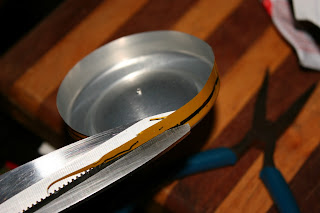


 Next I took a tin can and smacked a hole in it with my familys trusty meat mallet.


 And sanded down a small plastic bottle so that its contour matched the tin cans.
 Then cut a really big hole in the side of the small plastic bottle.
 All this, so I could glue the small plastic bottle on the side of the tin can with a big hole in the side.


